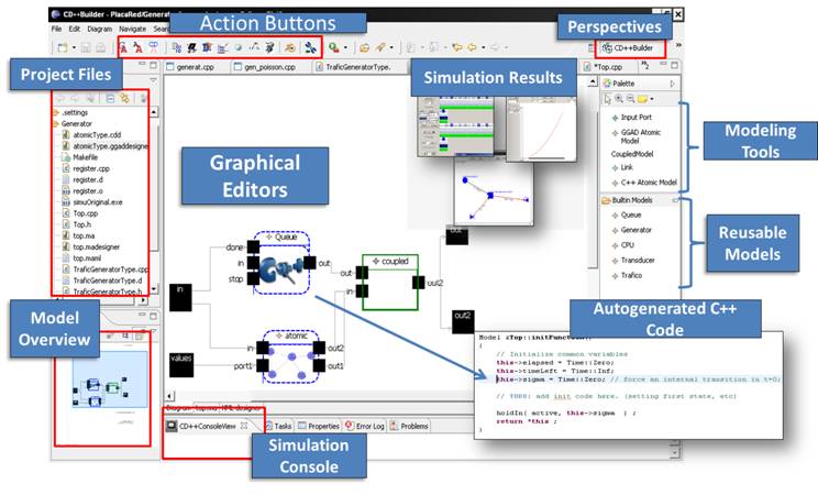
CD++Builder User Manual
This is a DRAFT user manual for the new facilities of CD++Builder. For comments or errors found, send an email to gwainer@sce.carleton.ca and we will update the manual with the necessary changes.
If you have trouble using CD + + Builder 2.0, check the bug tracker if you have resolved the problem or to load new faults. Bug Tracker: http://sourceforge.net/tracker/?group_id=235328&atid=1095931
Table of Contents
Defining a Project in Eclipse. 1
Defining internal coupled models. 9
Editing internal coupled models. 9
Defining atomic models (Built-in). 11
Building an atomic model using DEVS Graphs. 18
Defining External Transitions. 22
Defining Internal transitions. 24
Defining an atomic model using C++ (CPP files). 27
Importing the sample projects. 28
Defining a CD++ Project in Eclipse
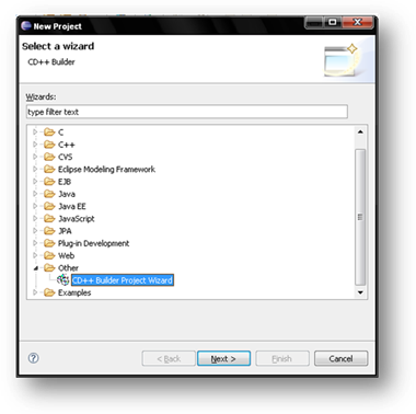
1. Start Eclipse
2. Go to File | New | Project ...
3. In the category DEVS choose CD++ Builder Project Wizard and click Next.
4. Insert the author's name and a name for the project (in these examples, we will use TestingProject)
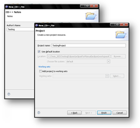
5. Click on Finish.
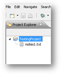
This generates an Eclipse project that will be available in the
Project Explorer panel.
Defining
Coupled Models
The following example (found in the distribution of CD++Builder) shows how to define a queuing model that transmits the values stored in a queue. The values in the queue are transmitted 1 time per second.
1. Right click on the project TestProject , new | Other to open the wizard (also from File | New | Other)
2. In the category DEVS, choose DEVS Coupled Model Diagram and click Next

3. Give it a model name and click Finish (in our case we will use automaticQueue.madesigner)
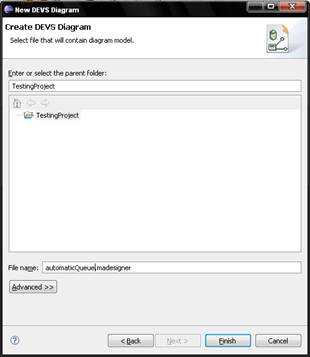
4. The result of this step is an empty coupled model ready to be populated.
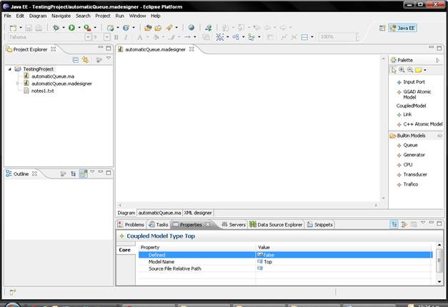
5. Editor areas:
Some General Tips:
·
Using Ctrl + mouse scroll wheel you can zoom in / out.
Also, using the buttons ![]() on the Palette of Modeling
Tools.
on the Palette of Modeling
Tools.
· In the Properties tab, one can be make visible any object by right clicking on it, and selecting Properties
·
You can choose the preferred code editor view with the flaps found
below the Editor window
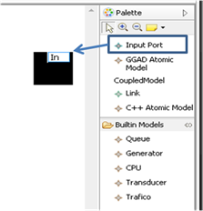
Defining a port
We will define 2 ports: 1 input and one output
1.
Click on the icon palette Input Port ![]() and click anywhere on the editor (you get a “+ at the arrow).
and click anywhere on the editor (you get a “+ at the arrow).
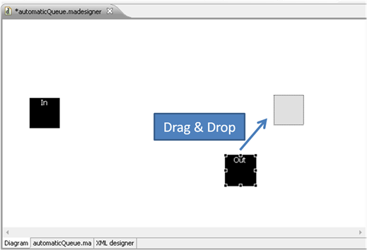
2. You will get a square representing the port. To give a name to the port, type the name (in this case, we put In). You can also change the name from the Properties tab
3. Repeat steps 1 and 2, but using the icon Output Port and put the name Out.
4. All items can be moved to either side of the editor, selecting and dragging them. For instance, we can move the port In to the left, and the port Out to the right.
5.
Save the file.
NOTE: you can save your file using ctrl + S, using the Eclipse Save button or the menu File | Save
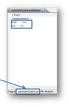
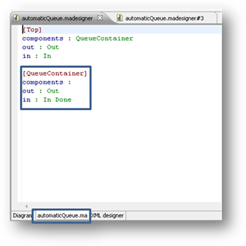
In order to verify the
contents, you can select the .ma
option in the editor tabs (in this case, choose AutomaticQueue.ma to see the text definition of the model)
Defining Internal coupled models
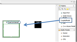
1.
Select the icon palette Coupled Model ![]() , and click on the Editor panel.
, and click on the Editor panel.
2. This will create an empty Coupled Model. We will name it QueueContainer .
Edit internal coupled models
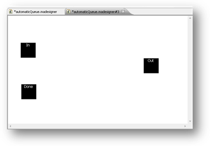
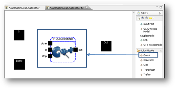
1. To edit the model QueueContainer, double click on the figure. This opens a new editor (similar to one discussed above)
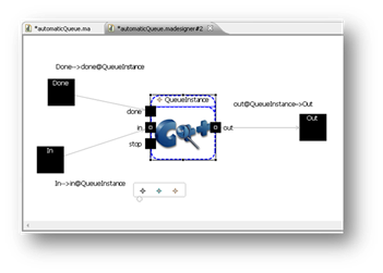
2. In the contained model (with a similar name as the parent coupled model) model we will add 3 ports as shown below: 2 input (In and Done) and 1 Output (Out; remember to change the port types in the properties tab)
3.
Save everything from the main model (automaticQueue.ma) and
verify that it was written well (reading the corresponding textual .ma file).
NOTE: the tab to read of .ma files is only available on the coupled models (internal models
do not have their own files, but they are a part of a higher level .ma file).
·
Note that the ports in the main model are displayed automatically.
If you change the ports of the content model, changes are kept (including
links).
Defining atomic models (Built-in)
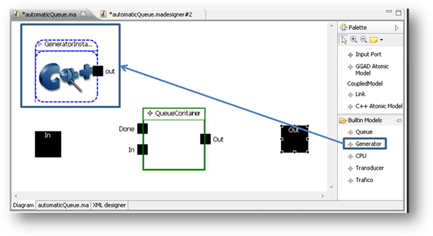
4. Go to the model editor QueueContainer, choose from the
palette Queue ![]() and click on the Editor pane. This will define a new atomic model
of type Queue.
and click on the Editor pane. This will define a new atomic model
of type Queue.
NOTE: The models shown as Built-in are registered in register.cpp (in this case, the internal version of register.cpp). If you change the register.cpp, the models changed will be displayed there. The ports and parameters are read from the .cpp files that define the models.
5.
Do the same, but in the model TOPadding a Generator ![]()
6. We must define the parameters for models GeneratorInstance and QueueInstance, which can be done using the Properties tab. For the generator will use the following values
preparation: 00:00:00:05
For the queue:
distribution: normal
mean: 2
deviation: 1
7.
Save, using the button ![]() .
.
Defining
Links
All you would need now is to link the ports.
1. Select the icon palette Link ![]()
2. Click and hold on the source port
or release the button on the destination port. (Note that the cursor changes from warning status according to the link’s – i.e., if it is valid or not -).
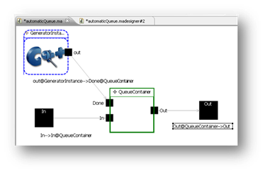
a. Define the following links in the top model:
· From In to ln@QueueContainer
· From out@QueueContainer to Out
b. Define the following links in the model QueueContainer:
· From In to ln@QueueInstance
· From Done to Donate@QueueInstance
· From Out@QueueInstance to Out
3. Save the changes.
Run
the simulation
To run the simulation is needed to file events.
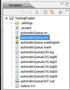
1. Defining a automaticQueue.ev within the project (File | New | File)
2. Copy this code:
00:00:00:00 in 1
00:00:00:01 in 2
00:00:00:01 in 3
00:00:00:01 in 4
00:00:00:01 in 5
00:00:00:01 in 6
00:00:00:01 in 8
00:00:00:01 in 9
00:00:00:01 in 10
00:00:00:01 in 11
00:00:00:01 in 12
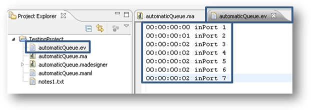
3. Save it in the event file automaticQueue.ev.
4. Click the Simulation button ![]()
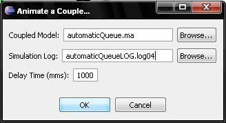
5. Complete the fields as shown in the figure below:
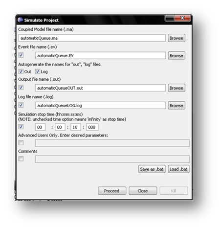
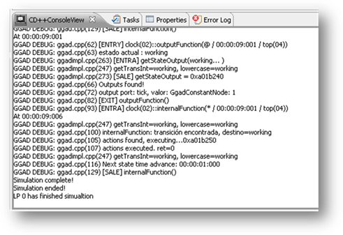
6. Click on Proceed, and the simulation will start. At the end of the simulation you will find the simulation log files
View
an animation
1.
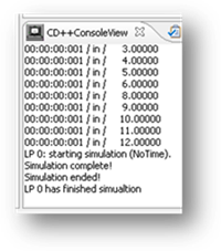
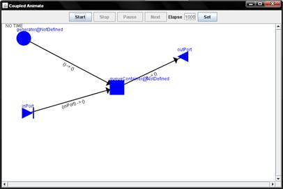
Click on the button to animate Coupled Model ![]()
2. completing the form as in Figure:
3. It will open the display animations CD++Modeler to visualize the simulation results of the models we defined.
Defining a model atomic DEVS-Graph
We will replace the Generator model that comes with the
simulator, and will define a DEVS atomic model-Graph with a similar
functionality.
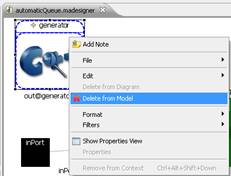
1. On our previous example, delete the model generatorInstance choosing it from the editor, right clicking it, and selecting Delete From Model.
2. We will now define a DEVS Graph Atomic Model using the DEVS model-choosing palette. Use the name Clock.
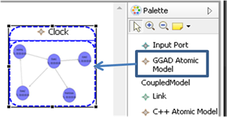
3. Double click on the model Clock for editing.
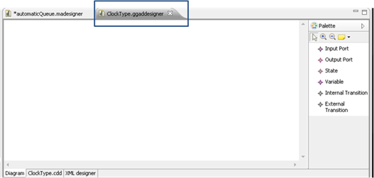
Defining a port
To define I/O ports for this model:
·
For Input ports, select Input Port ![]() from the palette, and click on
the Editor panel.
from the palette, and click on
the Editor panel.
·
For Input ports, select Output Port![]() from the
palette, and click on the Editor panel.
from the
palette, and click on the Editor panel.
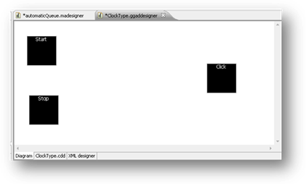
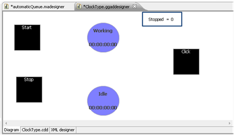
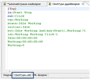
1. We will define 3 ports: 2 input (Start and Stop) and one output (Tick), as in the following picture.
Defining states
·
choose State ![]() from the palette, and click on the model Editor.
from the palette, and click on the model Editor.
· Give a name to the state
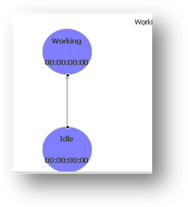
1. We will define 2 states: one Idle and the other Working
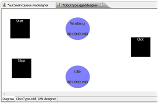
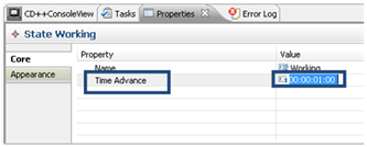
2. Define the Working state, using a TA value of 00:00:01:00 (using the Properties tab).
3.
Define the Idle state, using a TA value of infinity
(using the Properties
tab).
Defining Variables
·
Choose Variable ![]() from the palette, and click on the model Editor.
from the palette, and click on the model Editor.
· Give a name to the variable
1. We will define a variable named Stopped
Defining External Transitions
·
Choose External Transition ![]() from the palette, click on the state originating and drag
to the destination state.
from the palette, click on the state originating and drag
to the destination state.
· Define the Condition using the Properties tab.
·
Define the Action using the Properties tab
(optional)
1. We will define an external transition between Idle and Working
2. From the Properties tab, edit the Condition of the
transition using the button ![]()
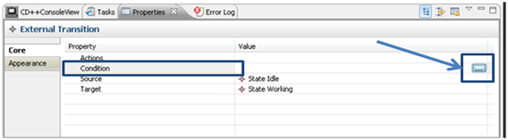
3. Complete the form as follows:
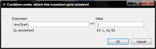
NOTE: This condition indicates that the transition will be executed for any value of the Start port (more complex models can use more complex expressions using the value of the variable)
4. From the tab Properties, edit the Actions of the
transition using button ![]()

5. Complete the form as follows (using the button Add to add the values):
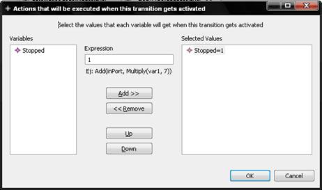
NOTE: This means that when the transition
is executed, the variable Stopped is set to 1.
Defining internal transitions
·
Choose Internal Transition ![]() , from the palette, and click on the source
state and drag to the destination state.
, from the palette, and click on the source
state and drag to the destination state.
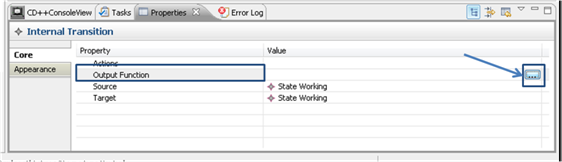
· Set the Output function from the Properties tab.
·
Define the Action from the Properties tab
(optional).
1. We will define an internal transition from Working to itself.

2. Edit the Output Function using the Properties tab
3. Complete the form as follows (using the button Add to add the values):
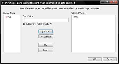
NOTE: this means that when the TA of
the Working state expires, we send the value 1 on the port Tick
4. Save the model and check the code generatedin the file ClockType.cdd
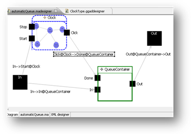
5. When we return to Model Top, the ports are automatically reflected in the coupled model
6. Now, we need to edit the coupled model to link the I/O ports with
the new DEVS-Graph model.
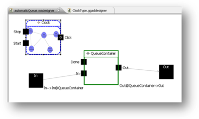
Define the following link as explained in Defining Links
· Define a link between In and Start@Clock
· Define a link between Tick@Clock and Done@QueueContainer
Run the simulation
To run the simulation and watch the animation is the same as you did with the coupled model simulation run.
NOTE: When simulating DEVS atomic
models-Graph, the executable of the simulator that is used is different.
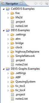
Examples
Importing the sample projects
This download includes a
workspace with examples of DEVS and DEVS-Graphs models ready to be used. This
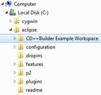
workspace is located in %eclipseInstallationDir%\CD++Builder
Example Workspace.
To use it, open Eclipse and select it perform the following steps:
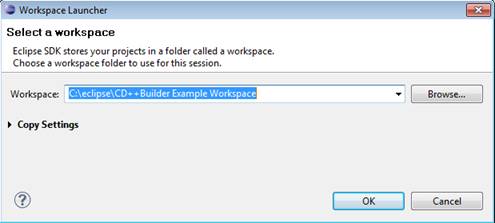
1. Choose File --> Switch Workspace --> Other... .
2. Then, choose in %eclipseInstallationDir%\CD++Builder Example Workspace.
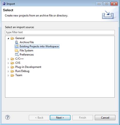
3. Choose File --> Import --> General à Existing Projects into workspace
4. Select all the projects in %eclipseInstallationDir%\CD++Builder Example Workspace.
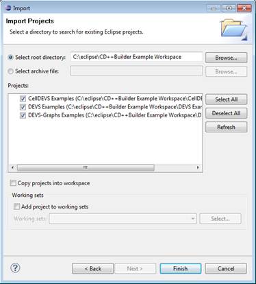
The example will appear on the Navigator view: